LOKASI : Kota Administrasi Jakarta Pusat
Bergabung Selama :
- Overcurren Relay MCGG 82, 52 dan 22
Produk atau jasa ini sudah tidak dijual, silakan hubungi perusahaan bersangkutan untuk keterangan lebih lanjut.
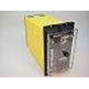
Overcurren Relay MCGG 82, 52 dan 22
Update Terakhir
:
16 / 12 / 2019
Dilihat Sebanyak
:
58 kali
Perhatian !
Perusahaan ini terdaftar sebagai Free Member. Hindari melakukan pembayaran sebelum bertemu penjual atau melihat barang secara langsung. COD (Cash On Delivery) atau bertemu langsung dengan penjual merupakan metode transaksi aman yang kami sarankan.
Detail Overcurren Relay MCGG 82, 52 Dan 22
MCGG 22
Single phase overcurrent with
instantaneous element.
MCGG 42
Two phase overcurrent with
instantaneous elements.
MCGG 52
Two phase overcurrent plus earth fault
with instantaneous elements.
MCGG 53
Two phase overcurrent ( with
polyphase measurement) plus earth
fault with instantaneous elements.
MCGG 62
Three phase overcurrent with
instantaneous elements.
MCGG 63
Three phase overcurrent ( with
polyphase measurement) , with
instantaneous element.
MCGG 82
Three phase overcurrent plus earth
fault with instantaneous elements.
Associated publications:
Midos System R6001
Directional Relay R6003
The relay can be used in applications
where time graded overcurrent and
earth fault protection is required.
The relay can be used to provide
selective protection for overhead and
underground distribution feeders.
Other applications include back-up
protection for transformers, generators
and HV feeder circuits and the
protection of neutral earthing resistors.
With all the current/ time
characteristics available on one relay,
a standard relay can be ordered
before detailed co-ordination studies
are carried out – a distinct advantage
for complex systems. Also, changes in
system configuration can be readily
accommodated.
An instantaneous element with low
transient overreach is incorporated
within each phase or earth fault
measuring board. This can be easily
disabled in applications where it is
not required.
For applications where the
instantaneous earth fault element is
required to have a sensitive setting
whilst remaining stable on heavy
through faults the use of a stabilising
resistor is recommended. The current
transformers for this application must
satisfy the criteria detailed under
‘ Current transformer requirements’ in
Technical Data.
The total impedance of the relay and
the series stabilising resistor is usually
low enough to prevent the current
transformers developing voltages over
2kV during maximum internal faults,
but in some applications a non-linear
resistor is required to limit this voltage.
Non-standard resistance values and
non-linear voltage limiting devices are
available.
Description
This range of MCGG relays is
designed so that versions are
available with separate measuring
boards for each phase or earth fault
input; alternatively, phase inputs may
be combined on to one board for
polyphase measurement ( see table) .
These boards, together with the other
circuits of the relay, are contained in
Switch position Operating
( 0) ( 1) characteristic
l
l Trip test
l
l
l Standard inverse sec SI
l
l
l Very inverse sec VI
l
l
l Extremely inverse sec EI
l
l
l Long time earth fault sec LT
l
l
l Definite time 2 seconds D2
l
l
l Definite time 4 seconds D4
l
l
l Definite time 8 seconds D8
l
Table1: Operating time characteristics with corresponding switch positions.
t =
0.14
( I0.02 – 1)
t =
13.5
( I – 1)
t =
80
( I2 – 1)
t =
120
( I – 1)
a single plug-in module which is
supplied in a size 4, 6 or 8 Midos
case. The case incorporates one or
two terminal blocks for external
connections. Removal of the module
automatically short circuits the current
transformer connections by means of
safety contacts within the case
terminal block. For added security,
when the module is removed, the ct
circuits are short circuited before the
connections to the output contacts and
the dc supply are broken. The relay
uses solid state techniques, each
measuring board utilising a microcomputer
as a basic circuit element.
The current measurement, whether
performed on a single phase or
polyphase input, is performed via an
analogue-to-digital converter.
Application diagrams are provided in
Figures 2 to 8 ( inclusive) showing
typical wiring configurations.
Each measuring board has a built-in
‘ power off’ memory feature for the
time delayed and instantaneous led
indicators.
Power to each measuring board may
be tested whilst the relay is in service.
without affecting the current
measurement. A test mode is also
available to carry out a trip test on the
output relays. During this test, current
measurement is inhibited.
When required, directional control
can be exercised over the relay by
connecting an output contact from
direction relay type METI to the
terminals provided.
Separate output contacts, capable of
circuit breaker tripping, are provided
for time delayed phase faults,
instantaneous phase faults, time
delayed earth fault and instantaneous
earth fault operations.
Relay settings
Separate setting switches for each
measuring board are provided on the
relay frontplate. These are used to
select the required time/ current
characteristic, current and time
multiplier settings.
Selection of time characteristics
The current/ time characteristic
selection is carried out by means of
three switches ( identified by
symbol on the nameplate) .
Table 1 gives the basic operating
characteristic and the settings of the
switches.
Tampilkan Lebih Banyak